SERVICES
Cathodic Protection System
Practical Application Of Cathodic Protection
With the simple theory of CP in mind, a preliminary discussion of the techniques of putting CP into actual use is given below. Details of each of these techniques are covered in later chapters.
Cathodic Protection with Galvanic Anodes
Cathodic Protection with Galvanic Anodes
Working Galvanic Anode of Zinc or Magnesium Buried in Earth and Connected to Pipeline with wire will Discharge current and Protect Pipeline as Shown.

Protected Pipeline.
The corrosion cell resulting from the contact of dissimilar metals In such a cell, one metal is active (negative) with respect to the other and corrodes. In CP with galvanic anodes, this effect is taken advantage of by purposely establishing a dissimilar metal cell strong enough to counteract corrosion cells normally existing on pipelines. This is accomplished by connecting a very active metal to the pipeline. This metal will corrode and, in so doing, will discharge current to the pipeline as shown in Images. In the case of CP with galvanic anodes, CP does not eliminate corrosion; rather, it displaces corrosion from the structure being protected to the galvanic anodes.
Under normal circumstances, the current available from galvanic anodes is limited. For this reason, CP by galvanic anodes normally is used where the current required for protection is small. Similarly, the driving voltage existing between pipe steel and galvanic anode metals is limited. Therefore, the contact resistance between the anodes and the earth must be low for the anodes to discharge a useful amount of current. This means that, for normal installations, galvanic anodes are used in low-resistivity soils.
A normal installation, as considered here, is one in which the current from a galvanic anode installation is expected to protect a substantial length of the pipeline. There are also instances where galvanic anodes are placed at specific points on a pipeline (often termed hot spots) and may be expected to protect only a few feet of pipe, especially where the line is bare.
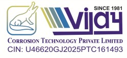
Driving Voltage Can Be Demonstrated By Connecting Anode And Unprotected Pipeline To Voltmeter As Shown. Typically, Pipeline Could Be Approximately 1.0 Volt Positive To Magnesium Anode And 0.5 Volt Positive To Zinc Anode.
Unprotected Pipeline.
To be free of the limited driving voltage associated with galvanic anodes, current from some outside power source may be impressed on the pipeline by using a ground bed and a power source. Images illustrate this situation. The most common power source is the rectifier. This device converts alternating current (AC) electric power to low-voltage direct current (DC) power. Rectifiers usually are provided with the means for varying the DC output voltage, in small increments, over a reasonably wide range. Although the maximum output voltage may be less than 10 V or close to 100 V, most pipeline rectifiers operate in the range between 10 and 50 V and can be obtained with maximum current outputs ranging from less than 10 A to several hundred amperes. This serves to illustrate the flexibility in the choice of power source capacity available to the corrosion engineer when planning an impressed current CP system.
Any other reliable source of DC electric power can be used for impressed current CP systems.
Cathodic Protection Consultancy
Cathodic Protection Consultancy
We have devoted a team of Cathodic Protection Specialist, Cathodic Protection, to provide a specialized wide range of services like
- Feasibilities surveys reports
- Temporary cathodic protection Design
- Permeate cathodic protection Design
- Oil Tank Anode Design
- Life Calculation of cathodic Protection of oil Tank, Water Heater, Heat Exchange, Bulet, Jitty & Other.
- Tendering assistance to clients
- Design and Engineering
- Design review and validation
- Installation Supervision & Testing and Commissioning
- Trouble shooting & Technical Audits
Manufacturing of Cathodic Protection Material
Manufacturing of Cathodic Protection Material
- Aluminium Anode with range varies from 20 gms to 150 kgs.
- Zinc Anode with range varies from 10 gms to 250 kgs.
- Magnesium Anode with range varies from 50 gms to 160 kgs.
- Hi-Si Anode with range varies from of 5 kgs to 300 kgs.
- Concrete Anode.
- Titanium Anode for ICCP System
- Water Heater & Heat Exchanger Magnesium Anode.
- Cathodic Protection Anode Box (TLP’s.).
- Copper-Copper (II) Sulphate Electrode Reference Cell .
- Ag AgCl Reference Cell .
- Half cell & Reference Cell.
- Mold Gun , Weld Powder.
- Earthing System.
- Polarization Cell for Pipeline .
- Surge Protection for pipeline .
- Corrosion Coupons for pipeline .